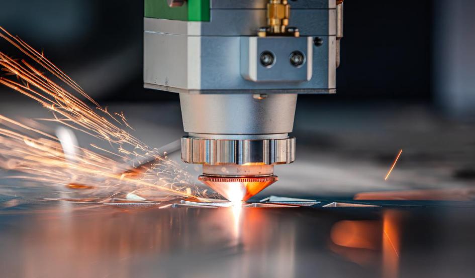
The Ultimate Laser Cutting Nozzle Selection & Troubleshooting Guide
-
July 20, 2026

-
9 min read

Failing to cut through your metal plates? Rough cross-sections? Heavy dross or slag adhering to the bottom edge? When these common production bottlenecks occur, machine operators often spend hours adjusting laser power, slowing down feed rates, or blaming the material.
Yet, even after consuming excessive assist gases and burning multiple protective windows, the cut quality remains poor and operating costs continue to spike. In most laser systems, the culprit behind these costly disruptions is a frequently overlooked, inexpensive part of your fiber laser consumables: the laser cutting nozzle.
In the highly competitive North American and European fabrication markets, experienced production managers know that selecting an incorrect or low-grade laser cutting nozzle triggers a costly chain reaction across the entire manufacturing line:
This comprehensive laser nozzle selection guide breaks down fluid dynamics, material composition, and calibration parameters to help you optimize your production.
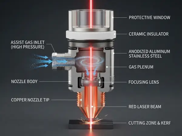
The fiber laser nozzle sits at the very bottom of the laser head, serving as the physical interface between the machine and the workpiece. Both the focused laser beam and the high-pressure assist gas pass through this tiny orifice.
Beyond gas shaping, the nozzle acts as the sensor tip for the capacitive height sensing system. The nozzle must maintain a precise, constant distance (standoff height, usually 0.5mm to 1.5mm) from the plate. If the nozzle's copper alloy has poor conductivity, the capacitive signal fluctuates, leading to height sensing instability and potential head crashes—a risk magnified in high-speed operations on a Robot Laser Cutting Machine.
The internal geometry of the laser cutting nozzle dictates laser nozzle gas flow dynamics. To clear molten metal effectively, the gas jet must remain a stable laminar flow. A clean, coherent laminar jet reaches deep into the kerf to eject molten slag.
If the nozzle interior is rough or damaged, the jet transitions into turbulent flow. Turbulence scatters the gas, widening the heat-affected zone (HAZ) and causing heavy slag to freeze on the bottom of the cut.
High-speed nozzles use a convergent-divergent (De Laval) internal geometry to accelerate the gas stream to supersonic speeds.
Best For: Cutting stainless steel and aluminum. The high-viscosity molten oxides of these materials are stubborn to remove. A supersonic jet provides the kinetic energy needed to sweep them away, resulting in a bright, dross-free edge.
These feature a simpler straight-bore or gently tapered design, producing subsonic gas speeds.
Best For: Thin sheets (under 3mm) and noise-sensitive shop environments. It delivers a gentle, uniform gas flow that minimizes surface spatter, making it a staple setting for a standard Flat Fiber Laser Cutting Machine. However, it lacks the velocity required for thick plate processing.
Understanding the difference between a single layer vs double layer nozzle is essential for selecting the correct cutting process:
| Technical Metric | Single Layer Nozzle | Double Layer Nozzle |
| Assist Gas | Nitrogen () / Compressed Air | Oxygen () |
| Cutting Mode | Fusion Cutting: Melts the metal via laser, relies purely on inert gas pressure to blow it away. | Oxidation Cutting: Oxygen reacts chemically with iron, generating extra heat to speed up the process. |
| Gas Jet Profile | High pressure, high flow rate. Focused, columnar jet. | Inner core controls oxygen flow to prevent overburn; outer layer stabilizes the boundary. |
| Primary Material | Stainless steel, aluminum, brass, copper. | Carbon steel (mild steel). |
Note on Specialized Designs: Storm/Boosted single-layer nozzles feature an outer shoulder to increase pressure without raising gas volume, commonly used in a High Power Fiber Laser Cutting Machine for high-efficiency stainless steel processing. High-speed double-layer nozzles feature a tapered tip with a larger inner core, designed specifically for clean, bright-edge cutting of mild steel.
Now that we understand the technical differences in nozzle designs, we can analyze the critical failure modes that occur when these configurations are misapplied or damaged.
When the nozzle orifice is too large, gas velocity drops at the exit, and the stream disperses.
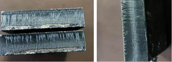
Result: The gas fails to deliver a concentrated blast. This causes rough striations on the cut surface, wide kerf widths, and heavy dross. Gas consumption also increases dramatically.
An undersized nozzle restricts the flow of assist gas into the kerf.
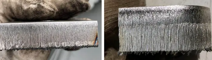
Result: Molten metal cannot be fully blown out, resulting in incomplete cuts or heavy slag adhesion. Furthermore, a smaller orifice increases the risk of the laser beam clipping the inner wall and makes the nozzle highly vulnerable to slag spatter.
Even a minor 0.1mm deformation or a tiny speck of spatter on the nozzle tip will distort gas symmetry. This leads to a frustrating directional defect where the cut is perfect when moving along the X-axis but shows heavy dross or fails to cut through when moving along the Y-axis.
Follow this practical, step-by-step approach to choose and calibrate the right nozzle for your machinery:
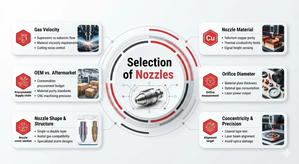
Step 1: Match Nozzle Structure to Gas and Material
Review the single layer vs double layer nozzle requirements. Always use single-layer nozzles for stainless steel, aluminum, or brass cut with nitrogen or compressed air. Use double-layer nozzles for carbon steel cut with oxygen.
Step 2: Evaluate OEM vs. Aftermarket Copper Laser Nozzles
When sourcing laser cutting nozzle replacements, decision-makers often weigh OEM performance against aftermarket pricing:
Step 3: Verify Copper Material Quality
Always specify high-purity tellurium copper (e.g., C14500) over cheap brass. Tellurium copper dissipates heat quickly, resists thermal deformation from molten spatter, and maintains a clean capacitive signal to protect your Height-Following Cutting Head.
Step 4: Match Orifice Diameter to Plate Thickness
Refer to this general laser nozzle diameter chart for process matching across sheets or profiles processed on a flate or tube fiber laser cutting machine:
Oxygen () Cutting for Mild Steel (Double Layer)
Nitrogen () Cutting for Stainless Steel (Single Layer)
Step 5: Perform Nozzle Centering Calibration
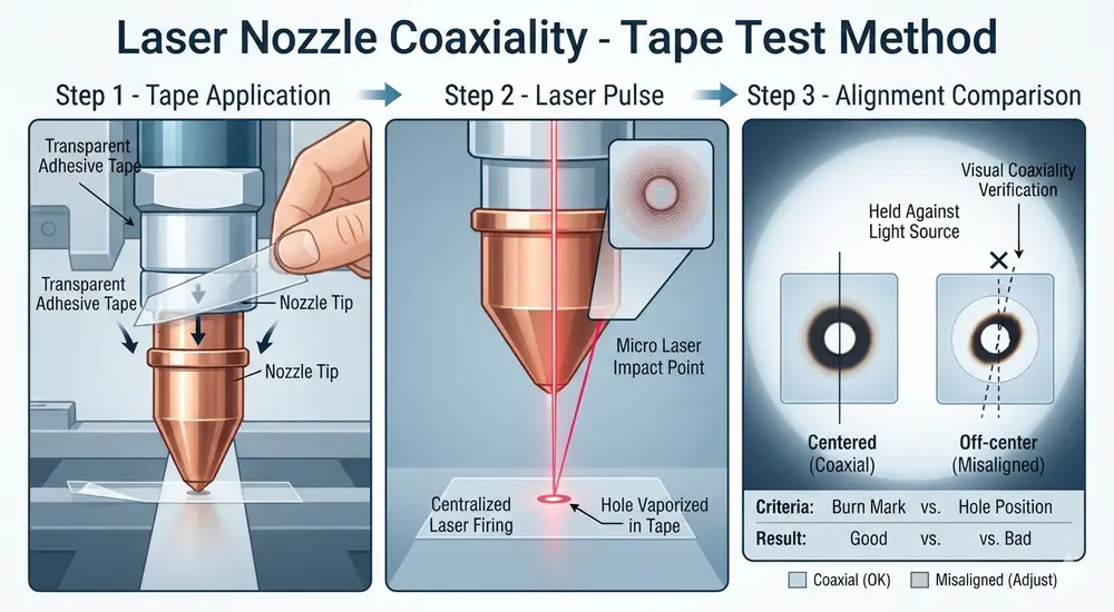
A high-quality laser cutting nozzle must maintain concentricity within mm to ensure the laser beam passes directly through the center of the gas stream.
💡 The Standard DIY nozzle centering calibration (Tape Test)
Operators should execute nozzle centering calibration daily before production:
While premium fiber laser nozzle components require a higher upfront investment, their long-term savings are significant:
The fiber laser nozzle is the vital gatekeeper of your cutting system. When selecting your laser cutting nozzle, evaluate your application's requirements against material quality, orifice size, OEM/aftermarket trade-offs, and concentricity. This laser nozzle selection guide serves as your blueprint to maximize your fiber laser nozzle efficiency and reduce the overall operating costs of your Fiber Laser Cutting Machine.
To further optimize your laser cutting operations and deepen your engineering knowledge, explore these related technical resources:





English

French

German

Hindi

Italian

Japanese

Korean

Portuguese

Russian

Spanish
Tell us about your manufacturing challenges.
Our engineers will design a laser solution tailored to your exact requirements.