What Determines 3D Five-Axis Laser Cutting Accuracy? Machine, Fixture, Calibration and Part Variation
-
August 27, 2026

-
24 min read

Accuracy is one of the first specifications buyers compare when evaluating a 3D five-axis laser cutting machine.
A specification sheet may list:
These values are important.
But they do not tell you directly whether a hole on a hot-formed B-pillar, a trim line around a curved component or an angled slot on a hydroformed tube will meet the tolerance on your drawing.
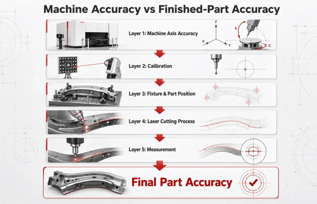
That is because final 3D laser cutting accuracy depends on the complete production system.
It is influenced by:
In a five-axis machine, errors can also interact.
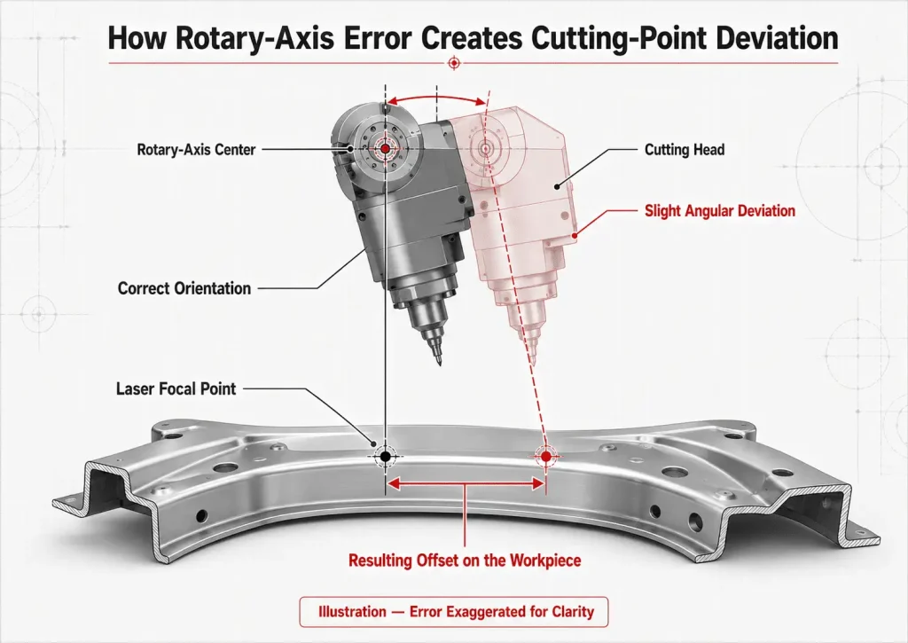
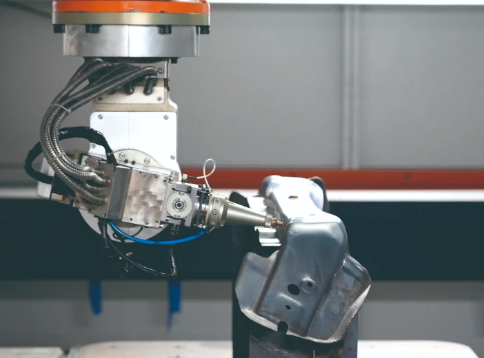
A small angular error in the cutting head may create only a small deviation when the nozzle is close to the rotational center but a larger positional deviation when projected over a greater distance.
Renishaw notes that once two rotary axes are added to three linear axes, the machine controller must accurately know the location of the rotary-axis pivot points so that the tool tip can be positioned correctly relative to the workpiece.
Therefore:
Machine positioning accuracy is not the same as finished-part accuracy.
The correct way to evaluate a five-axis laser project is to understand the entire accuracy chain and then verify it on representative parts.
Before comparing specifications, separate several different concepts.
Positioning accuracy describes how closely a machine axis reaches a commanded position.
For example, if the CNC commands an axis to move to a specific coordinate, positioning accuracy describes the difference between the commanded and actual position.
Repeat positioning accuracy describes how consistently the axis returns to the same location during repeated movements.
A machine can be highly repeatable but still contain a systematic positional offset.
For example:
The machine may repeat the location consistently while still requiring calibration.
In a five-axis machine, rotary-axis errors matter because cutting-head orientation changes continuously.
An angular error can change:
Cutting accuracy describes the result of the actual laser process, not only axis movement.
It includes effects from:
Finished-part accuracy is what the customer ultimately cares about.
It is measured on features such as:
This is the result of the complete manufacturing process.
Most five-axis laser machines use three primary linear axes:
These axes control the position of the cutting head within the machine workspace.
Possible linear-axis errors include:
Renishaw’s current machine-tool metrology guidance treats linear positioning, straightness, angular errors and multi-axis interpolation as separate contributors to overall machine accuracy.
Imagine that the cutting head follows a long contour across a formed automotive component.
A small X-axis positioning deviation may shift the trim line.
But if the head is also:
the final error becomes dependent on several axes simultaneously.
This is why five-axis performance cannot be evaluated using only the accuracy of one linear axis.
Rotary axes differentiate five-axis cutting from conventional flat-sheet laser cutting.
The exact axis names vary by machine architecture, but a five-axis cutting head commonly includes two rotary movements in addition to X, Y and Z.
These rotary axes control cutting-head orientation.
Suppose a rotary axis has a small angular deviation.
At the rotation center, the positional effect may be very small.
But as the distance between the rotation center and laser focal point increases, angular deviation produces a greater linear displacement at the cutting point.
Conceptually:
Angular Error + Tool Length = Cutting-Point Position Error
This is why identifying and calibrating rotary-axis pivot points is critical in multi-axis machinery.
Renishaw specifically identifies rotary-axis positioning, alignment and mechanical errors as important error sources in five-axis machines.
One of the most important concepts in five-axis cutting is the Tool Center Point, commonly abbreviated as TCP.
The control system must know the precise relationship between:
As the head rotates, the CNC coordinates the linear axes so that the laser remains on the programmed cutting path.
If TCP calibration is incorrect, rotating the head can cause the focal point to move away from the intended position.
You may see:
Calibration may deserve attention after:
TRUMPF’s current 3D laser systems include dedicated functions for checking positioning accuracy because even minor nozzle collisions can shift the cutting optics enough to increase reject rates without the operator immediately noticing the change.
This illustrates an important production principle:
Calibration is not only a commissioning task. It is part of maintaining process capability.
The machine may move correctly while the cutting process itself is no longer centered correctly.
Important cutting-head factors include:
The laser beam should be correctly centered relative to the nozzle.
Poor centering can produce asymmetric gas flow and affect:
The correct focus depends on:
If focal position drifts, the machine may still follow the correct geometric path while the cut quality deteriorates.
TRUMPF’s calibration systems specifically monitor focal position and recognize long-term and temperature drift as factors that can move the real focus away from the programmed condition.
Even a minor contact between:
should not automatically be treated as harmless.
After a collision, verify:
A common mistake is to treat the fixture as a simple accessory.
For 3D laser cutting:
The fixture is part of the measurement and positioning chain.
A highly accurate machine cannot produce consistently accurate components if the fixture does not locate the workpiece consistently.
The fixture should establish a clear datum strategy.
The objective is to prevent uncontrolled movement while avoiding unnecessary over-constraint.
Depending on part geometry, positioning may use:
Ask:
If the operator loads the same part ten times, does the part occupy the same coordinate position each time?
That is more useful than simply asking whether the fixture “holds the part tightly.”
TRUMPF’s 3D laser cutting guidance also treats fixture generation and workholding as an integrated part of 3D processing rather than a separate downstream consideration.
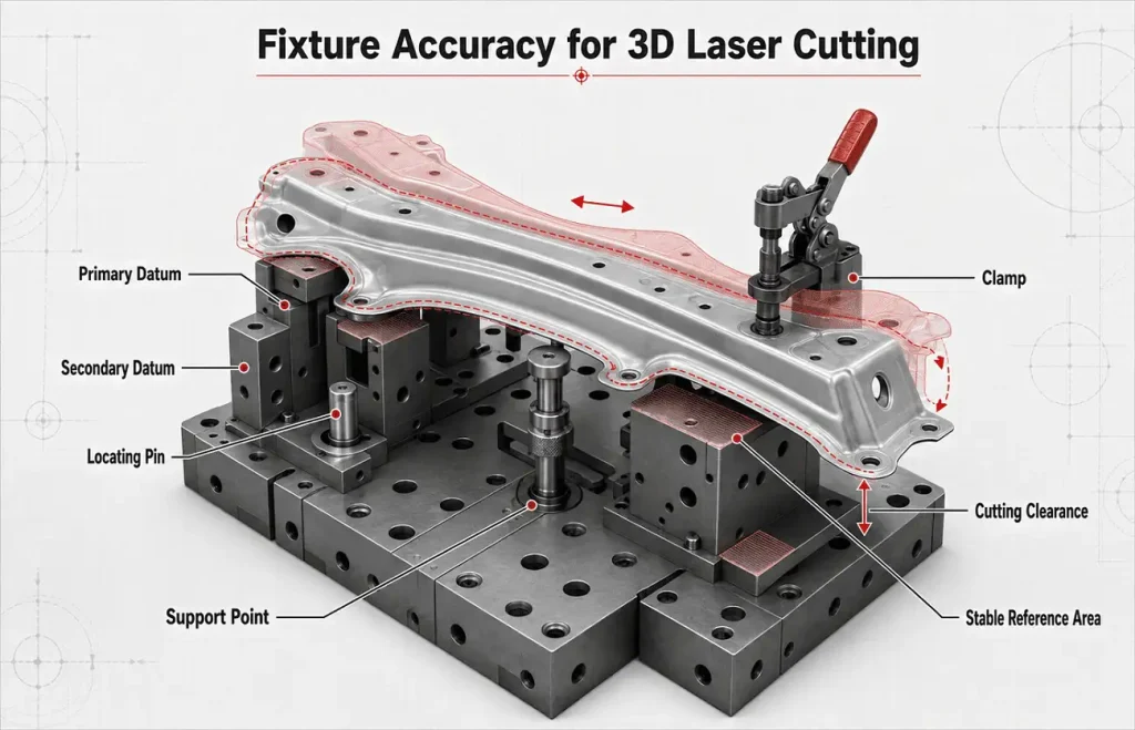
A clamp must secure the component.
But excessive clamping can reduce accuracy.
This is particularly important with:
Excessive force may push a component into the nominal CAD geometry while it is clamped.
After cutting and unclamping, the component may relax into a different shape.
This creates a difficult situation:
The part appears accurate on the fixture but fails measurement in free state.
The fixture should locate the component—not reshape it unless the engineering specification explicitly defines inspection in the constrained condition.
Even when a five-axis machine is perfectly calibrated, incoming parts are not necessarily identical.
This matters because five-axis laser cutting often processes parts after another forming operation.
Examples include:
Hot stamping is particularly attractive in automotive production because it can achieve complex geometry with very low springback compared with many cold-formed high-strength steels. ArcelorMittal highlights good geometric accuracy and reduced or minimal springback as key characteristics of press-hardened steels.
But this does not mean every production part is mathematically identical.
Real production still requires control of:
The CAM system normally generates the cutting path from nominal geometry.
The physical part may differ slightly.
If the variation is small relative to the allowable tolerance, the process may remain acceptable.
If the tolerance is tighter than the incoming variation, the project may require:
Suppose a formed component varies slightly in overall shape.
Where should that variation be absorbed?
The answer depends on datum strategy.
Imagine a long automotive reinforcement with critical mounting holes at one end.
If the component is located from the opposite end, length variation may shift the critical hole position.
A different datum strategy may keep the critical features stable while allowing variation to appear in a less important trimming area.
Ask:
The laser fixture should follow the engineering logic of the component rather than simply selecting the easiest place to install clamps.
Not every dimension needs the same tolerance.
Classify features:
Critical
General
This helps the application engineer prioritize accuracy where it creates value.
The machine, fixture and CAD model must share a consistent coordinate system.
Typical references may include:
If these are not aligned correctly, the entire cutting program may shift.
These problems are different from random machine repeatability errors.
A systematic offset should normally trigger a coordinate and calibration investigation before process parameters are changed.
Five-axis laser cutting requires more than drawing a 2D contour.
The software determines:
TRUMPF’s 3D programming system, for example, imports 3D CAD data and generates three-dimensional cutting proposals specifically for this type of multi-axis processing.
Problems may arise from:
The head orientation can influence:
Two programs following the same nominal trim line may produce different results if they use different cutting-head orientations.
The mathematically ideal cutting-head orientation is not always physically possible.
The cutting head must avoid:
The programmer may need to change head orientation to create sufficient clearance.
This means fixture design, accessibility and accuracy are interconnected.
For example:
A clamp placed too close to a critical hole may require the cutting head to approach at an unfavorable angle.
Moving the clamp may improve:
without changing the machine.
This is why the machine, fixture and program should be evaluated as one system.
A geometrically perfect machine can still produce an inaccurate finished edge if the cutting process is unstable.
Important variables include:
TRUMPF’s 3D cutting guidance identifies laser power, focus, speed, gas pressure and piercing strategy as key cutting parameters used together to achieve the required process result.
The programmed laser path may need an offset to account for kerf width.
If kerf compensation is wrong:
Depending on the process, cutting direction and head angle can influence the finished edge.
This becomes particularly relevant when inspecting a feature at tight tolerance.
Assist gas is primarily used to remove molten material from the kerf.
But poor gas delivery can indirectly affect dimensional results by producing:
Three-dimensional surfaces create additional challenges because the nozzle may not remain perpendicular to the local surface.
Variables include:
A parameter validated on a flat coupon should not automatically be assumed to produce the same result on a recessed 3D feature.
Industrial machines operate for hours or multiple shifts.
During this time:
These effects can produce gradual drift.
Renishaw includes thermal distortion among the error sources that influence multi-axis machine performance.
TRUMPF similarly identifies temperature drift as one reason focal position may move away from the required location over time.
A sample cut immediately after commissioning does not automatically prove long-term production stability.
A severe collision is obvious.
A minor nozzle contact may not be.
The operator may see:
but the cutting head or optics may have shifted slightly.
TRUMPF explicitly warns that small nozzle collisions can cause minor positioning errors that are not visible to the operator and can result in increased scrap. Its ObserveLine system is designed to periodically check machine positioning for exactly this reason.
Consider checking:
Do not immediately compensate the NC program for a machine that has physically moved out of calibration.
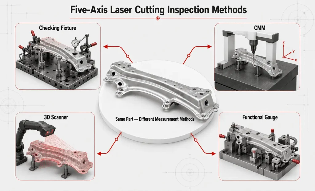
Accuracy is meaningless unless measurement conditions are defined.
A complex formed component may be measured:
These methods may produce different results.
A thin formed panel may sit slightly differently when:
Therefore, the drawing and quality plan should define how the finished component will be accepted.
If production locates the part using one datum system but quality control measures from an unrelated reference, apparent errors may be introduced.
Engineering, production and quality teams should therefore agree on:
before the machine acceptance test.
A machine may cut one good part.
That does not prove the production process is stable.
A buyer evaluating mass production should distinguish:
Can the machine produce the required geometry once?
Can it produce similar results repeatedly?
Can the complete production process stay within the specified tolerance over continued production?
Process capability includes more than machine motion.
It includes:
For critical production, the acceptance plan may require repeated sample parts rather than a single demonstration piece.
For engineering discussion, final part deviation can be thought of conceptually as:
Final Part Deviation ≈ Machine + Calibration + Fixture + Workpiece + Cutting Process + Measurement
This is not a mathematical tolerance formula.
The errors cannot simply be added together because:
However, the model is useful because it prevents one common mistake:
blaming every dimensional problem on machine positioning accuracy.
A hole shifts 0.4 mm between two production parts.
Possible causes include:
The investigation should identify which part of the chain changed.
Use a structured process.
Possible causes:
Investigate systematic errors first.
Possible causes:
Possible causes:
Possible causes:
Possible causes:
Do not correct geometric errors by randomly changing cutting parameters.
| Problem | Possible Cause | First Check |
|---|---|---|
| Entire contour shifted | Coordinate or fixture offset | Workpiece zero and fixture |
| Hole position changes with head angle | TCP or rotary calibration | Five-axis calibration |
| Same part loads differently | Fixture repeatability | Locating surfaces and clamps |
| Hole diameter incorrect | Kerf compensation | Cutting parameters |
| One side accurate, other side offset | Part geometry or datum strategy | Incoming part and fixture |
| Accuracy changes after collision | Cutting-head shift | Calibration |
| Accuracy changes during long production | Thermal drift | Verification and environment |
| Good on fixture, bad after unclamping | Clamping deformation | Fixture force |
| Different results between parts | Incoming part variation | Measure blanks/formings |
| CMM and checking fixture disagree | Measurement datum | Inspection method |
Improvement should start with the dominant error source.
Accuracy improvement is therefore usually a system optimization task, not simply a machine-parameter adjustment.
Do not specify the tightest possible tolerance on every feature.
Every unnecessary tolerance can increase:
Separate features into categories.
Examples:
Examples:
Examples:
A tolerance should reflect the functional requirement of the component.
The purchasing question is not:
“What is the smallest tolerance your machine can claim?”
It should be:
“Can the complete process repeatedly meet the tolerances that matter on my part?”
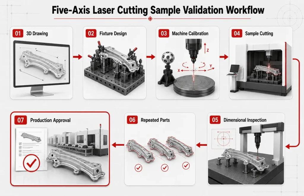
For five-axis projects, brochure specifications are not enough.
A representative sample test provides information about:
Whenever possible, provide:
The test part should include:
For serious production projects:
one part tests feasibility
while:
multiple parts begin to evaluate repeatability.
Do not record only cutting speed.
Document:
This creates a repeatable engineering record rather than a marketing demonstration.
Consider a specification such as:
Repeat Positioning Accuracy: ±X mm
It tells you something important about machine motion.
It does not automatically mean:
Every feature on every 3D workpiece will be within ±X mm.
The finished result also includes:
For comparison, TRUMPF publishes separate values for linear-axis positioning accuracy and rotary-axis positioning accuracy on its 3D laser platforms, while also providing independent machine-position monitoring and optics setup functions.
This illustrates the correct way to interpret specifications:
machine-axis data describes the machine
while:
sample inspection verifies the production result.
ZG Laser similarly publishes machine-motion specifications on its five-axis product pages, but actual achievable part tolerance should be confirmed according to the customer’s geometry, fixture and process rather than inferred directly from one specification value.
Hot-formed automotive components are one of the most important five-axis laser applications.
Typical parts include:
The cutting system may need to create:
These components often enter highly repeatable downstream assembly processes.
Therefore, accuracy evaluation should consider:
ZG Laser’s current five-axis product range is specifically positioned around hot-formed automotive components and complex 3D trimming.
A related question is whether a dedicated five-axis machine is automatically more accurate than a robot.
The answer depends on the actual systems.
A dedicated five-axis machine and articulated robot have different motion structures.
Factors include:
The correct comparison is therefore not based on architecture alone.
It should use:
Five-axis laser cutting vs robotic laser cutting
Before purchasing a machine, ask:
The supplier should explain the accuracy process, not only quote the smallest number on the specification sheet.
Before approving a five-axis laser project, confirm:
3D five-axis laser cutting accuracy is not determined by one specification.
The machine’s linear and rotary axes provide the foundation, but final part accuracy also depends on:
This is why:
positioning accuracy should not be treated as a guaranteed finished-part tolerance.
For a real production project, the most reliable method is to provide the actual 3D part, define the critical dimensions, design the fixture, calibrate the complete system and verify the result through repeated sample cutting.
The question buyers should ask is not:
“What is your machine accuracy?”
It is:
“Can this complete process repeatedly produce my actual part within the required tolerance?”
That is the more meaningful definition of five-axis laser cutting accuracy.
Send ZG Laser:
Our application team can evaluate:
before recommending a machine configuration.
Send Your 3D Drawing for Evaluation
Explore 3D Five-Axis Laser Cutting Machines
Q1: What determines five-axis laser cutting accuracy?
Final accuracy depends on linear and rotary axes, machine geometry, TCP calibration, cutting-head condition, fixture repeatability, workpiece variation, cutting parameters and measurement method.
Q2: Is machine positioning accuracy the same as cutting accuracy?
No. Positioning accuracy describes machine-axis movement. Finished-part cutting accuracy also includes rotary-axis behavior, fixture, workpiece geometry, kerf, process parameters and inspection.
Q3: What is TCP in five-axis laser cutting?
TCP means Tool Center Point. The control system must know the exact position of the cutting point relative to the machine’s rotary axes so that the focal point remains on the programmed path as the head rotates.
Q4: Why is rotary-axis calibration important?
A small angular error can create a positional error at the laser focal point. Renishaw identifies rotary-axis position, alignment and pivot-point calibration as important contributors to five-axis machine accuracy.
Q5: Can the fixture affect laser cutting accuracy?
Yes. If the fixture locates the part differently between cycles, the cutting path will be applied to a differently positioned workpiece even when the machine repeats perfectly.
Q6: Can excessive clamping reduce accuracy?
Yes. Excessive clamping can deform thin or formed components, creating dimensions that change after the part is released.
Q7: Why does accuracy change after a cutting-head collision?
A collision may shift the nozzle, cutting optics or calibrated cutting-head relationship. TRUMPF specifically monitors machine positioning because even minor nozzle collisions can create unnoticed positioning errors.
Q8: Does higher laser power improve cutting accuracy?
Not necessarily. Laser power affects process capability, but geometric accuracy depends on many other factors. Excessive or poorly optimized energy can also reduce edge quality.
Q9: How should five-axis accuracy be tested?
Use the actual or representative 3D component, a production-style fixture and agreed inspection datums. Measure critical features and cut several repeated samples when production stability is important.
Q10: How often should a five-axis machine be calibrated?
There is no universal interval for every machine. Calibration frequency should follow the machine manufacturer’s recommendations and production requirements, with additional verification after collisions, major maintenance or unexplained dimensional changes.
Q11: Can part sensing compensate for incoming workpiece variation?
Depending on the machine and sensing system, probing, vision or other measurement methods may be used to locate parts or apply corrections. The required capability should be defined according to the actual variation and tolerance.
Q12: What accuracy should I request when buying a five-axis laser machine?
Start from the finished-part drawing. Define critical tolerances and the inspection method, then ask the supplier to demonstrate those requirements through sample testing rather than selecting equipment solely from the smallest positioning-accuracy figure.
Recommended Related Readings
For more practical guidance on laser equipment maintenance, troubleshooting, performance optimization, and failure prevention, explore the related technical resources below. These articles provide additional engineering insights to help you improve machine reliability, efficiency, and long-term performance.




English

French

German

Hindi

Italian

Japanese

Korean

Portuguese

Russian

Spanish
Tell us about your manufacturing challenges.
Our engineers will design a laser solution tailored to your exact requirements.