How to Design Fixtures for 3D Five-Axis Laser Cutting
-
September 3, 2026

-
27 min read

A high-precision five-axis laser cutting machine does not automatically produce an accurate finished component.
The machine can follow the programmed path correctly while the final trim line or hole position is still wrong if the workpiece is:
For this reason, fixture design is a fundamental part of a 3D laser cutting project.
This is particularly important for:
A good fixture must solve several problems at the same time.
It must:
Traditional fixture-design principles remain useful. Carr Lane identifies accurate referencing, repeatable locating and avoiding redundant location as fundamental workholding principles, while Renishaw’s fixturing guidance similarly uses the 3-2-1 principle to establish stable primary, secondary and tertiary datums.
However, 3D laser cutting adds another requirement that conventional machining fixtures do not always face to the same degree:
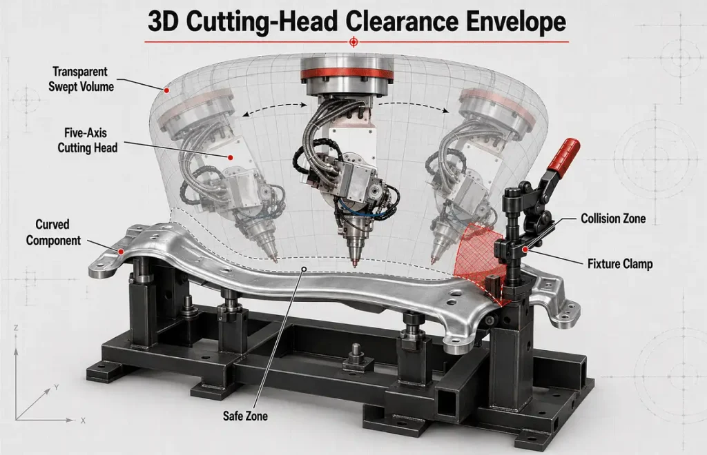
The fixture must leave a clear three-dimensional movement envelope around the entire laser cutting head.
This guide explains how to design around all of these requirements.
A fixture has three main functions:
It establishes the position and orientation of the workpiece relative to the machine coordinate system.
It prevents the component from sagging, rocking or changing position under gravity, clamping or part release.
It keeps the component against the intended locating points during the cutting cycle.
These functions should not be confused.
A clamp should not be used to compensate for poor locating.
A support should not accidentally become an uncontrolled datum.
And adding more contact points does not automatically improve accuracy.
The fixture should create a clear and repeatable relationship:
Machine → Fixture → Workpiece → Cutting Path
If that relationship changes, the cut changes even when the CNC program remains identical.
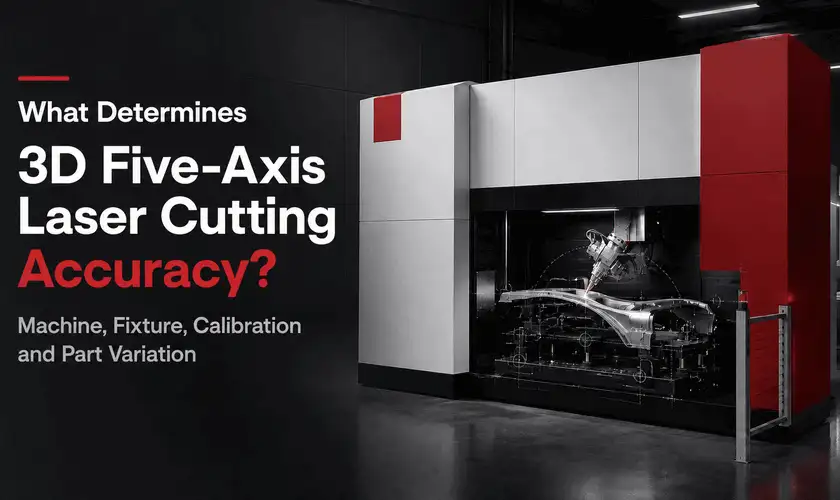
What determines 3D five-axis laser cutting accuracy
A common mistake is to start fixture design by asking:
“Where can we put the clamps?”
The better question is:
“Which features determine how this component functions and how it will be inspected?”
Before designing the fixture, review:
The fixture datum strategy should generally relate to the functional datum system of the component.
Suppose a B-pillar contains:
If the assembly holes are functionally critical, the fixture should not be designed around an unstable flange simply because it is convenient to clamp.
Otherwise, forming variation at that flange may shift every critical cut feature.
Separate the drawing into:
Critical features
General features
This helps determine where positional accuracy matters most.
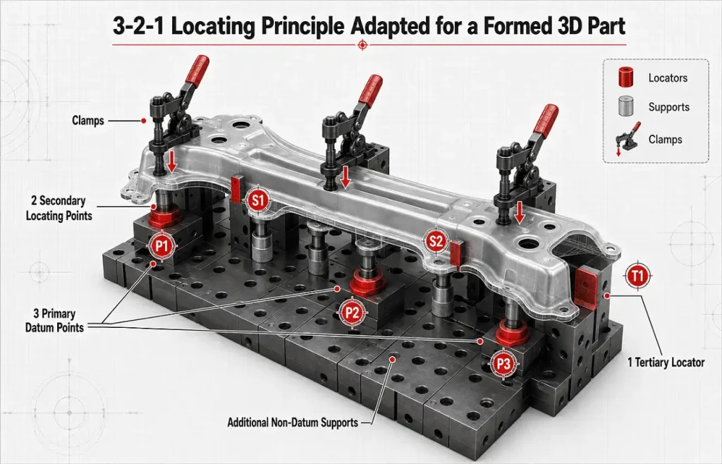
The classical 3-2-1 locating principle is a useful starting point for fixture design.
In a simplified rigid workpiece:
Together, they establish the workpiece position and orientation.
Renishaw’s fixture guidance describes the same structure using three primary contacts, two secondary contacts and one tertiary contact for repeatable fixturing.
Carr Lane likewise describes the 3-2-1 method as a basic approach for controlling workpiece movement through six properly selected locating points.
A large hot-formed sheet-metal component is not the same as a rigid machined block.
The part may contain:
Additional support points may therefore be necessary.
The key distinction is:
Additional supports do not necessarily need to become additional datums.
You can support a flexible area without allowing every support to independently determine the part position.
Otherwise, the fixture can become over-constrained.
The best locating surface is not necessarily the largest surface.
It should be the feature that provides the most consistent reference between parts.
Possible locating features include:
Existing holes can provide strong positional references when:
A common approach uses:
rather than two rigid round pins that can create binding when hole spacing varies.
A formed surface can be used when:
Edges can be useful, but assess:
Do not locate a precision cutting operation from a feature whose incoming position is less stable than the tolerance you are trying to achieve.
More locators may appear safer.
In reality, unnecessary locators can reduce consistency.
Carr Lane specifically warns against redundant location, where more than one locator attempts to control the same degree of freedom. Because real production parts vary, they may not contact all redundant locators simultaneously, creating inconsistent seating.
Imagine a curved component supported by four rigid pads intended to define one plane.
If the real component varies slightly:
The fixture now has several possible seating conditions.
Use:
The fixture should tell the part exactly where to sit.
It should not give the part several competing answers.
This distinction is especially important for large thin-walled 3D parts.
Locators define the workpiece position.
Their position should be:
Supports prevent:
They do not always need to define the datum.
Consider a long formed automotive reinforcement.
Three points may establish its primary reference plane, while several other supports carry flexible sections.
If every support is made rigidly height-critical, normal forming variation may prevent the workpiece from seating properly.
Possible alternatives include:
The correct solution depends on production variation and tolerance.
This is one of the most important principles for formed-part laser trimming.
A component may not match nominal CAD geometry perfectly.
If the fixture uses powerful clamps to force every area against a theoretical surface, the component may appear correct while clamped.
After cutting and unclamping, it can spring back.
The result may then fail inspection.
Therefore:
A fixture should locate the production part consistently, not mechanically recreate the CAD model unless the product specification explicitly requires constrained positioning.
This is particularly important for:
TRUMPF’s guidance for secondary processing of formed components specifically identifies securing parts with repeatable positioning while processing them without deformation as a key challenge in this application.
Laser cutting is a non-contact process.
Unlike milling, drilling or mechanical punching, there is no conventional cutting tool pushing heavily against the workpiece.
Therefore, the fixture usually does not require the same high clamping forces associated with heavy machining.
The clamps primarily need to:
Too much force can:
Where practical, clamping force should push the component:
toward its locating surfaces
rather than sideways away from them.
The locating elements establish position.
The clamp maintains that position.
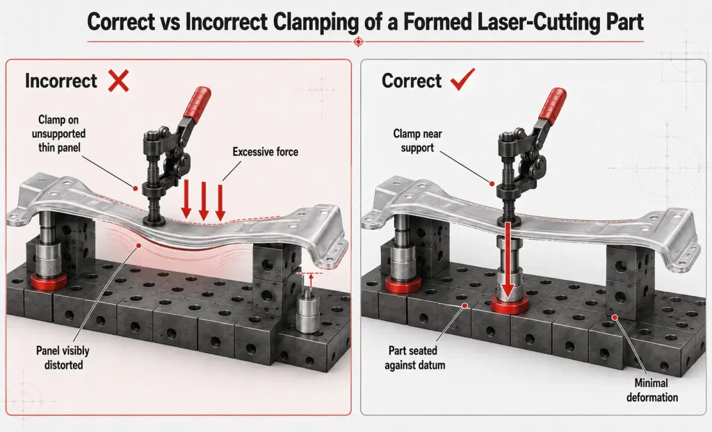
A clamp pressing on an unsupported flexible surface may bend the part.
Where possible:
Clamp toward a support or locator.
Avoid configurations where:
Poor design:
Clamp ↓
Thin sheet
Large unsupported gap
Support
This can deform the panel.
Better design:
Clamp ↓
Part
Support directly below or nearby
The clamp then seats the part without unnecessarily bending it.
This is where a five-axis laser fixture differs fundamentally from many conventional fixtures.
The cutting head does not simply move vertically above the component.
It may:
The fixture must therefore provide a 3D access envelope, not only clearance around the laser beam.
Do not simulate only:
Include:
A clamp may be 40 mm away from the trim line and still cause a collision because the upper body of the tilted cutting head passes through that space.
A clear path at 0° does not mean the fixture is accessible at:
ZG Laser’s current five-axis platforms are designed specifically for multi-direction trimming, holes, contours and bevels on formed and irregular workpieces, which makes fixture clearance part of the complete five-axis application rather than a separate issue.
A useful fixture-design method is to create a keep-out volume around the programmed cutting path.
Instead of asking:
“Is this clamp close to the trim line?”
ask:
“Will any part of the five-axis head occupy this volume during the complete programmed movement?”
The digital model should include:
Fixture components should remain outside this envelope wherever possible.
Pay particular attention near:
Do not complete the fixture first and only then ask the programmer to make the laser path fit.
That workflow often creates unnecessary compromises.
A better process is iterative:
Part CAD
→ Preliminary Cutting Path
→ Fixture Concept
→ Head Accessibility Simulation
→ Fixture Revision
→ Final Path
→ Collision Validation
Suppose a clamp blocks access to an assembly hole.
Possible solutions include:
The best solution cannot be determined by the fixture designer or programmer independently.
This is why fixture design and offline programming should be treated as one engineering process.
The digital simulation model should contain more than the workpiece.
Include:
The earlier the fixture exists as a proper 3D model, the easier it is to detect interference before manufacturing.
A programmer may model a clamp only as a small rectangular block.
The real clamp may include:
One of these can become the real collision point.
For five-axis processing, the simulation model should represent the geometry that actually occupies space.
The nozzle must maintain the appropriate relationship with the workpiece surface.
Fixture design can interfere with this when:
The fixture should maintain the workpiece in a predictable location so the height-control system operates within its intended range.
This becomes more challenging around:
Accessibility should therefore be evaluated at the nozzle and cutting-head level—not only by checking whether the laser beam theoretically reaches the contour.
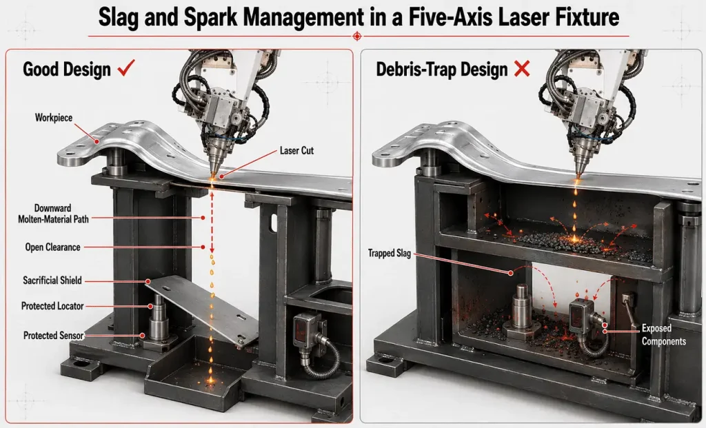
The laser removes material from the cutting kerf.
That material must go somewhere.
Fixture designers should consider the direction of:
Do not position critical:
directly in the expected slag path where practical.
Repeated exposure can lead to:
Where possible, allow:
Do not create closed pockets that gradually fill with cutting debris.
Some fixture areas cannot avoid exposure.
Instead of allowing expensive structural components to absorb repeated sparks and slag, add replaceable protection.
Possible components include:
Design these components so that they can be:
A sacrificial part should not become an uncontrolled datum as it wears.
Keep precision locating elements functionally separate from expendable protective components where possible.
A formed component may contain residual stress.
As material is trimmed away, its stiffness and stress distribution can change.
Possible effects include:
Therefore, fixture design cannot always be separated from cutting sequence.
If a large perimeter trim is completed first, the part may lose support before several critical holes are cut.
An alternative sequence may be:
The best sequence depends on the component.
Ask:
After this section is removed, what still supports the remaining component?
A support located under scrap rather than the finished component may disappear functionally halfway through the cycle.
Real formed parts vary.
The fixture needs to accommodate the expected process variation without introducing inconsistent positioning.
Possible variation includes:
If possible, select the most stable manufacturing features as references.
May be useful when:
Carr Lane identifies adjustable and equalizing supports as methods for accommodating workpiece surfaces where fixed supports are unsuitable.
For applications with meaningful variation, the cell may also use:
Renishaw describes part setting as establishing the position of datum features and work coordinate systems before machining; the same general manufacturing principle is useful when evaluating whether a variable incoming 3D part requires automated positional verification.
Whether this is necessary depends on:
Part sensing is useful.
But it should not be used as an excuse for unstable workholding.
A sensing system can potentially identify:
It cannot necessarily correct:
Use sensing to measure controlled variation.
Do not use it to compensate for an uncontrolled fixture.
Fixture design also depends on machine architecture.
A fixed-table fixture may suit:
Priorities include:
A rotary-table system can support:
But the fixture must also withstand:
The fixture and component must remain stable during movement.
ZG Laser’s current five-axis portfolio includes platforms intended for both flexible processing and higher-cycle automotive production, so fixture concepts should follow the production architecture rather than use one universal design.
If operators will load the component manually, fixture ergonomics affect productivity.
Consider:
A fixture can include mistake-proofing features so the component:
Carr Lane describes foolproofing as an important fixture-design principle and notes that strategically placed locating features can prevent incorrect orientation.
Reducing loading errors is often more valuable than reducing theoretical loading time by one or two seconds.
If a robot will load the part, fixture access must work for both:
the laser cutting head
and
the handling robot or gripper.
The fixture must consider:
A clamp placement that is ideal for manual loading may block the robot gripper.
Therefore, automated fixtures should be developed together with:
May be suitable for:
Benefits include:
But the result may depend more on operator technique.
Can support:
Important considerations include:
May be appropriate for selected heavy fixtures but often adds complexity unnecessary for lightweight sheet-metal laser trimming.
Choose the actuation system according to the real holding requirement—not simply because more force is available.
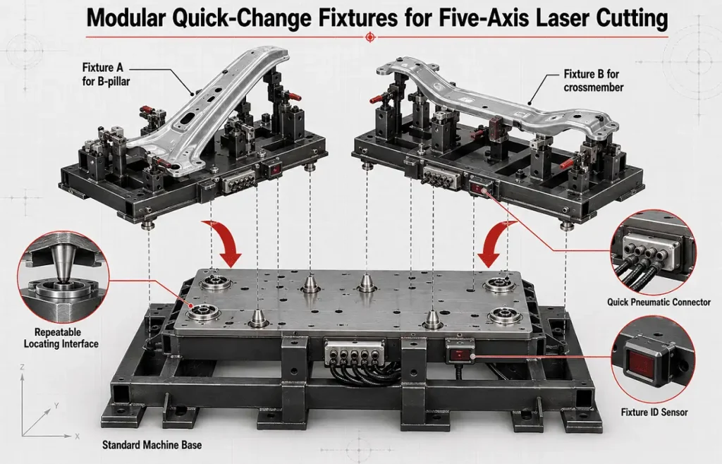
One advantage of five-axis laser cutting is product flexibility.
That advantage can disappear if changing fixtures takes hours.
For multiple product variants, consider standardized:
Fast changeover has little value if every change requires lengthy re-teaching.
The fixture should return to a known relationship with the machine coordinate system.
Depending on production requirements, changeover may include:
Fixture construction should balance:
Possible materials include:
Locating pins and datum elements may require:
Fixture frames should remain stable under:
But unnecessary mass can make:
Design only the stiffness the application requires.
Do not assume that a well-machined fixture is repeatable.
Test it.
A practical fixture validation can include:
This helps separate:
fixture loading variation
from:
machine cutting variation.
After the fixture itself is evaluated, load several real parts.
This helps identify the difference between:
If one part repeats well but different parts do not, the incoming geometry may be the dominant issue.
Fixture tolerances should support the finished-part requirement.
Not every fixture component needs ultra-tight tolerances.
Critical elements include:
Less critical elements may include:
Over-specifying the entire fixture increases:
without necessarily improving final accuracy.
The tolerance strategy should follow the actual dimensional chain.
Production fixtures change over time.
Common issues include:
A good fixture should make these areas easy to:
Consider replaceable:
Rather than rebuilding the complete fixture after wear.
Avoid deep pockets where:
can accumulate unnoticed.
A small piece of debris on a datum pad can shift the entire component.
For production applications, fixture maintenance should not depend on an operator noticing a problem.
Define checks such as:
Inspect:
The interval should depend on:
| Problem | Likely Cause | Improvement Direction |
|---|---|---|
| Part loads differently each cycle | Unclear datum or unstable locator | Review locating strategy |
| Part rocks in fixture | Insufficient or poorly placed supports | Improve support layout |
| Part distorts when clamped | Excessive force or unsupported clamp area | Reduce force and support near clamp |
| Laser head hits clamp | Fixture designed without full head envelope | Simulate complete 5-axis motion |
| Hole position varies between parts | Incoming-part variation or locating inconsistency | Measure incoming parts and datums |
| Good while clamped, bad after release | Fixture forcing component into shape | Reduce over-constraint |
| Slag builds on locator | Locator placed in cutting path | Add shield or relocate locator |
| Sensors fail frequently | Direct spark/slag exposure | Protect or reposition sensor |
| Long fixture changeover | No standardized base/interface | Use modular quick-change concept |
| Wrong part loaded | No foolproofing | Add asymmetric locator or detection |
| Program works on one fixture but not another | Fixture-to-machine reference variation | Improve repeatable fixture mounting |
| Finish changes after several hundred parts | Wear or contamination | Establish maintenance checks |
A structured fixture-development process can follow these stages.
Collect:
Identify:
Determine:
Choose stable features that support the dimensional requirements.
Control:
without unnecessarily over-constraining the component.
Clamp toward locators using the minimum effective force.
Simulate all required orientations.
Protect:
Evaluate:
Include all collision-relevant geometry.
Check:
Verify critical fixture datums.
Measure:
Fixture development should include allowance for adjustment after real sample testing.
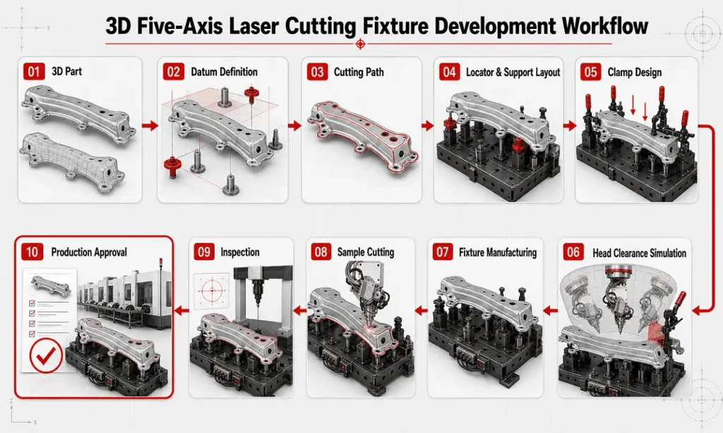
Fixture validation should answer four separate questions.
Check:
Repeat the loading operation several times.
Measure reference positions.
Compare:
Run:
The fixture should pass all four before production approval.
A fixture should not be considered finished simply because it matches CAD.
The real validation happens with:
Fixture
Machine
Cutting
Inspection
One part may prove that the fixture physically works.
Repeated parts begin to show whether the fixture is stable enough for production.
Hot-formed automotive components are one of the most important applications for dedicated five-axis laser trimming.
Typical parts include:
These parts create several fixture challenges:
The fixture should therefore balance:
accuracy + access + cycle time
rather than optimize any one factor independently.
For repetitive automotive production, the fixture may also include:
A dedicated five-axis machine and robotic laser cutting cell may require different fixture layouts.
The fixture must fit within:
This makes the working envelope relatively predictable.
A robot fixture may be installed:
This offers more layout freedom but introduces:
Both architectures still depend on consistent locating.
Fixture design becomes much more efficient when the customer supplies complete engineering data.
Provide:
For formed parts, physical production samples are extremely valuable.
The nominal CAD model cannot always reveal:
Fixture engineering should therefore use both:
nominal CAD
and
representative real parts.
Before approving a project, ask:
A good fixture proposal should explain the location strategy, not simply show an attractive 3D rendering.
Before approving a fixture, confirm:
Fixture design is not a secondary detail in 3D five-axis laser cutting.
It is part of the cutting system.
The machine can only apply the programmed path accurately when the workpiece occupies a known and repeatable position.
A successful fixture therefore requires more than simply holding the component tightly.
It must:
The most important principle is:
The fixture should locate the part—not force the part into shape.
And for five-axis processing:
Every clamp, locator and support must be evaluated not only against the part, but against the complete movement envelope of the cutting head.
For this reason, the best fixture-development process combines:
part engineering + fixture design + offline programming + collision simulation + sample cutting + dimensional inspection
before production begins.
Send ZG Laser:
Our application team can evaluate:
before the final machine and fixture configuration is confirmed.
Send Your 3D Drawing for Evaluation
Explore 3D Five-Axis Laser Cutting Machines
What Determines 3D Five-Axis Laser Cutting Accuracy?
Q1: Why is fixture design important in five-axis laser cutting?
The fixture establishes the workpiece position relative to the machine. If the part is positioned differently between cycles, the laser follows the same programmed path on a differently located component.
Q2: What is the 3-2-1 principle in fixture design?
The classical 3-2-1 principle uses three primary, two secondary and one tertiary locating contacts to establish a workpiece position and orientation. Additional supports may be required for large or flexible formed parts.
Q3: Should a laser cutting fixture clamp the part tightly?
It should clamp securely, but excessive force can deform thin or formed parts. Laser cutting is non-contact, so the fixture normally needs enough force to maintain reliable locating rather than the high forces associated with heavy machining.
Q4: Can too many locating points reduce accuracy?
Yes. Redundant locating points can create competing contacts when real parts vary, leading to inconsistent seating.
Q5: Should clamps be placed close to the laser cutting path?
Only when complete cutting-head clearance has been verified. A clamp can be clear of the laser beam but still collide with the body of a tilted five-axis cutting head.
Q6: How do you prevent fixture deformation of thin parts?
Use stable locating points, sufficient support and the minimum effective clamping force. Place clamps near supported areas and avoid using force to push the component into nominal CAD geometry.
Q7: How should a fixture accommodate hot-formed part variation?
Use stable production datums and separate locating functions from additional support. Depending on the application, adjustable supports or part sensing may also be evaluated.
Q8: Should the fixture be included in offline programming?
Yes. The digital model should contain clamps, locators, supports, fixture structure and other collision-relevant elements so the complete five-axis head movement can be simulated.
Q9: How can slag damage a fixture?
Molten material and debris can accumulate on locators, damage sensors and alter seating surfaces. Fixtures should provide open clearance and sacrificial protection around high-exposure areas.
Q10: How do you test fixture repeatability?
Repeatedly load and clamp the same component, measure reference positions, unload it and repeat the process. Then compare multiple production parts to distinguish fixture variation from incoming-part variation.
Q11: Do five-axis laser fixtures need maintenance?
Yes. Locators can wear, slag can accumulate, clamps can change and sensors can become damaged. Production fixtures should have scheduled cleaning and inspection.
Q12: Should the fixture be finished before laser programming begins?
No. Fixture and cutting-path development should be iterative because clamp position, support geometry and cutting-head orientation directly affect one another.




English

French

German

Hindi

Italian

Japanese

Korean

Portuguese

Russian

Spanish
Tell us about your manufacturing challenges.
Our engineers will design a laser solution tailored to your exact requirements.